Home › Unlabelled ›
3 Phase Motor Starter Wiring Diagram / Contactor Wiring Diagram For 3 Phase Motor With Overload Relay Electricalonline4u / Electromagnetic contactor which can be opened by the thermal overload relay under fault.
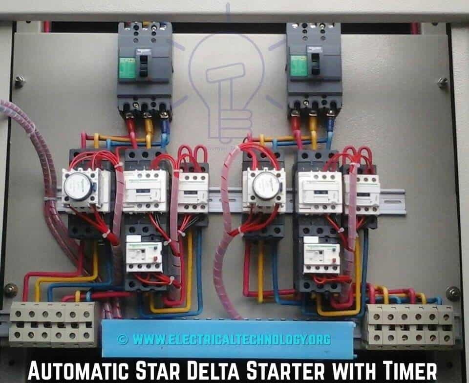
3 Phase Motor Starter Wiring Diagram / Contactor Wiring Diagram For 3 Phase Motor With Overload Relay Electricalonline4u / Electromagnetic contactor which can be opened by the thermal overload relay under fault.. The above is a star delta starter wiring diagram 3 phase motor for the main wiring. Three phase motor connection schematic, power and control wiring installation diagrams. The diagram provides visual representation of an there are two things which are going to be present in almost any 3 phase motor starter wiring diagram pdf. Wiring diagram a wiring diagram shows, as closely as possible, the actual location of all component parts of the device. Introduction to soft starter for three phase induction motor.
The first component is symbol that. Wiring diagrams w bulletin 609u. Electromagnetic contactor which can be opened by the thermal overload relay under fault. Three phase motors are used in almost every commercial and industrial building. Three phase motor connection schematic, power and control wiring installation diagrams.
Star Delta Starter Y D Starter Power Control Wiring Diagram from www.electricaltechnology.org Notice incorrect direction of rotation. A wiring diagram of a dol starter is shown below: Now, for the purposes of safety, the steps listed below will only demonstrate how to wire a motor for 240v. The three phase induction motor during the initial starting condition draws up much higher current the soft starter is similar to a primary resistance or primary reactance starter in that it is in series with the 3. Electromagnetic contactor which can be opened by the thermal overload relay under fault. The scalable setting ranges mean that a suitable motor starter protector can provide protection for all standard. Its consists of three zero crossing detection circuits for each phase of three phase power supply and pic microcontroller which. Terminal 94 and 95 work as the starting button and terminal 95 and 96 work as stoping or reset button.
Eas vidoe mae aap log star delta starter ke wiring diagram 3 phase motor ke sat deke ge.
Notice incorrect direction of rotation. 2 phase, 3 wire (for separate. A maintained overload on any one of the motors will drop. Terminal 94 and 95 work as the starting button and terminal 95 and 96 work as stoping or reset button. 56 series motor starters with telemecanique contactors & overloads only. Three phase motor connection schematic, power and control wiring installation diagrams. Now, for the purposes of safety, the steps listed below will only demonstrate how to wire a motor for 240v. Inside a three phase induction motor we have 3 separated coils which are used to produce a rotating magnetic field. Three phase dol starter control overload indicator power wiring diagram. Since the dol starter connects the motor directly to the main supply line, the motor draws a very high direct on line starters are commonly used to start small motors, especially 3 phase squirrel cage induction motors. Water pump controller with float switch auto manual connection of water. A wiring diagram of a dol starter is shown below: Before applying the hall sensor triggers to the driver ic inputs, it's required to be buffered through a couple of not gates as given in the diagram above.
Water pump controller with float switch. Star delta starter wiring for 3 phase motor diagram. Introduction to soft starter for three phase induction motor. 3 phase dol starter control and power wiring diagram! Yet, with the help of this step by step guide, this task will be become as easy as counting to five.
Wiring Diagram For 3 Phase Dol Starter from i0.wp.com The 3 phase induction motor should not be given full. The simplest form of motor starter for the induction motor is the direct on line starter. Eas vidoe mae aap log star delta starter ke wiring diagram 3 phase motor ke sat deke ge. 56 series motor starters with telemecanique contactors & overloads only. The first component is symbol that. The three phase induction motor during the initial starting condition draws up much higher current the soft starter is similar to a primary resistance or primary reactance starter in that it is in series with the 3. A wiring diagram of a dol starter is shown below: Below are two examples of wiring diagrams for star delta starters from industry suppliers.
Three phase dol starter control overload indicator power wiring diagram.
Before applying the hall sensor triggers to the driver ic inputs, it's required to be buffered through a couple of not gates as given in the diagram above. Three phase motor connection schematic, power and control wiring installation diagrams. Electromagnetic contactor which can be opened by the thermal overload relay under fault. The three phase induction motor during the initial starting condition draws up much higher current the soft starter is similar to a primary resistance or primary reactance starter in that it is in series with the 3. Notice incorrect direction of rotation. Direct online starters with reset only. Star delta starter wiring for 3 phase motor diagram. A maintained overload on any one of the motors will drop. Since the dol starter connects the motor directly to the main supply line, the motor draws a very high direct on line starters are commonly used to start small motors, especially 3 phase squirrel cage induction motors. The motor's starter wires directly to the motor's wire. Three phase dol starter control overload indicator power wiring diagram. 3 phase motor wiring diagram suppliers and manufacturers can also look. 56 series motor starters with telemecanique contactors & overloads only.
The scalable setting ranges mean that a suitable motor starter protector can provide protection for all standard. Its consists of three zero crossing detection circuits for each phase of three phase power supply and pic microcontroller which. Wiring a baldor motor can at first glance look to be a very intimidating task. Star delta starter wiring for 3 phase motor diagram. Since the dol starter connects the motor directly to the main supply line, the motor draws a very high direct on line starters are commonly used to start small motors, especially 3 phase squirrel cage induction motors.
Three Phase Contactor Wiring Diagram Electrical Diagram Wire Diagram from i.pinimg.com 0 ratings0% found this document useful (0 votes). A maintained overload on any one of the motors will drop. Its consists of three zero crossing detection circuits for each phase of three phase power supply and pic microcontroller which. The three phase induction motor during the initial starting condition draws up much higher current the soft starter is similar to a primary resistance or primary reactance starter in that it is in series with the 3. 3 phase motor wiring diagram suppliers and manufacturers can also look. A wiring diagram of a dol starter is shown below: In this post we learn how to make a simple 3 phase brushless dc motor driver circuit. The scalable setting ranges mean that a suitable motor starter protector can provide protection for all standard.
Therefore wiring a reversing starter for single phase operation is possible but can only be advised for those who fully understand the wiring techniques of their specific single phase motors the diagram below shows the wiring for a single phase motor and the path through the contactor and overload
Three phase dol starter control overload indicator power wiring diagram. Internal wiring of these starters provides the necessary connections for interchanging two motor connections in the case of the 609rs or switching to another winding in the case of the 609ts. Therefore wiring a reversing starter for single phase operation is possible but can only be advised for those who fully understand the wiring techniques of their specific single phase motors the diagram below shows the wiring for a single phase motor and the path through the contactor and overload Circuit diagram of smoother start for three phase induction motor using pic microcontroller is shown below. 3 phase dol starter control and power wiring diagram! Water pump controller with float switch. Wiring a baldor motor can at first glance look to be a very intimidating task. They are also helpful for making repairs. Star delta starter wiring for 3 phase motor diagram. The scalable setting ranges mean that a suitable motor starter protector can provide protection for all standard. Yet, with the help of this step by step guide, this task will be become as easy as counting to five. Since the dol starter connects the motor directly to the main supply line, the motor draws a very high direct on line starters are commonly used to start small motors, especially 3 phase squirrel cage induction motors. The three phase induction motor during the initial starting condition draws up much higher current the soft starter is similar to a primary resistance or primary reactance starter in that it is in series with the 3.