Home › Unlabelled ›
Water Level Alarm Circuit Diagram - Simple Water Level Indicator With Alarm 3 Tested Circuits Electronic Circuit Design Electronic Circuit Projects Circuit - Some homes have a large water tank on high, then pumping up the put on hold.
Water Level Alarm Circuit Diagram - Simple Water Level Indicator With Alarm 3 Tested Circuits Electronic Circuit Design Electronic Circuit Projects Circuit - Some homes have a large water tank on high, then pumping up the put on hold.. Water level alarm | circuit diagram here is the schematic of a water level alarm circuit. Here is a simple water level alarm circuit using 555 timer that will produce an audible alarm when the water level reaches a preset level.the circuit can be powered of a 3v battery and is very handy to use. When arduino water level sensor is continuously exposed to. Whenever tank gets filled, we get alerts on particular levels. Algorithm for water level controller circuit first configure the controller pins p0.0, p0.1 and p0.2 as inputs and p0.7 as output.
The circuit sends an acoustic alarm when it senses a drop of water leak. Check out the water level indicator circuit too! It is built around two bc547 transistors (t1 and t2) and two timer 555 ics (ic1 and ic2). This is a very simple project for water tank for saving water or. An alarm is also featured in this circuit.
Simple Water Level Indicator With Alarm 3 Tested Circuits Electronics Mini Projects Electronics Projects Diy Electrical Projects from i.pinimg.com The water level indicator circuit diagram monitors the level of water in the tank and simultaneously switches on the water pump whenever the water level goes low in the water tank. The circuit for a water level detector is shown below. When both the legs are dipped in water an electric path is created between the two legs and sensor start conducting current. Here is a simple level switch circuit that switches on one relay and switches off another relay when the fluid level exceeds the set limit.this circuit is a modification of the simple water level indicator previously posted.when the water level touches the probes positive supply is connected to the base of q1 through fluid.this makes transistor. If between the electrodes is a electricity conductor, for example an aqueous solution, then because of the rectification action of d1 and d2, the c4. Whenever tank gets filled, we get alerts on particular levels. Some homes have a large water tank on high, then pumping up the put on hold. The value of conductance/current depends on the ratio or level of water.
The circuit will work as a water level sensor and will give a melodious alarm sound when the two probes in the circuit will detect water.
Before starting the design process of this circuit, let's give you a brief explanation of the uln 2003 ic. The circuit sends an acoustic alarm when it senses a drop of water leak. To avoid the loss of overflow water we (electronic engineers) can take a step by the way of simple water level indicator alarm circuit. The water level of the tank is indicated by using the 5 led's and if the water level in the tanker is full then the water pump is turned off completely. Initially there is no voltage applied to the base of the transistor q1 and the transistor is in off state and no current is flowing through collector and emitter and led is off (see below diagram to understand transistor pin structure). Here is a simple level switch circuit that switches on one relay and switches off another relay when the fluid level exceeds the set limit.this circuit is a modification of the simple water level indicator previously posted.when the water level touches the probes positive supply is connected to the base of q1 through fluid.this makes transistor. Water level indicator is a type of indicator which shows us level of water at each lavel by visualizing by led or other display component. Automatic water pump controller circuit diagram. This schematic diagram shows a water level sensor/detector/monitor circuit. When arduino water level sensor is continuously exposed to. Pin 1 is connected to the ground. Water level indicator using ic uln 2003. In this circuit, we have used all the transistors as a switch.the water touches the wires' contact with base of each transistor, a small current flows through the base and turns on the transistor as the transistor turns on, the led connected to it glows.
This schematic diagram shows a water level sensor/detector/monitor circuit. This circuit is powered through the emitter current of the bc109c. A circuit that offers visual indication of fluid level in a vessel, with a switchable audible alarm. Components used in these projects areas: This simple water level sensor circuit monitors the presence of water in a certain location or container.
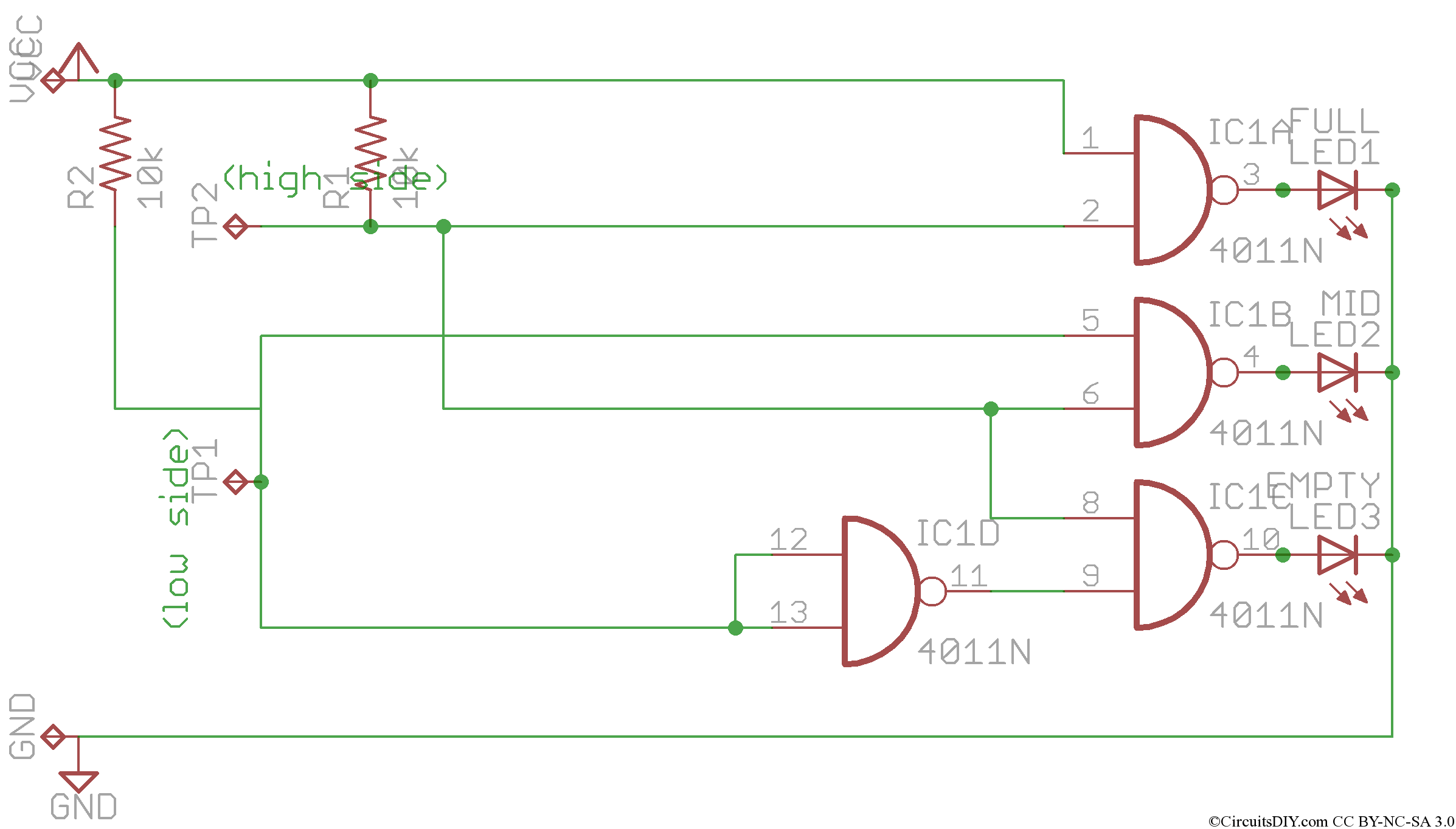
Simple Water Level Indicator Circuit Using Logic Ic Circuits Diy from www.circuitsdiy.com This schematic diagram shows a water level sensor/detector/monitor circuit. The circuit can be implemented to fit other applications as well that require liquid level measurement. The circuit for a water level detector is shown below. Water level indicator is a type of indicator which shows us level of water at each lavel by visualizing by led or other display component. Automatic water pump controller circuit diagram. Check out the water level indicator circuit too! Algorithm for water level controller circuit first configure the controller pins p0.0, p0.1 and p0.2 as inputs and p0.7 as output. Before starting the design process of this circuit, let's give you a brief explanation of the uln 2003 ic.
This simple water detector circuit uses alternative voltage in order to prevent the corrosion of the electrodes.
Both ic1 and ic2 are wired in astable multivibrator mode. To avoid the loss of overflow water we (electronic engineers) can take a step by the way of simple water level indicator alarm circuit. Pin 2 and pin 6 are shorted and connected to pin 7 through 570 ohm resistor. The circuit is using two ics and few other discrete components. Here is a simple water level alarm circuit using 555 timer that will produce an audible alarm when the water level reaches a preset level.the circuit can be powered of a 3v battery and is very handy to use. The circuit can be implemented to fit other applications as well that require liquid level measurement. Generally, water stored in overhead tank is wasted due to over flow ,when the tank is full. Also read the interesting concept about how water level alarm circuit works using 555 timer. In the below diagram water sensor circuit and how it works is broadly highlighted. An alarm is also featured in this circuit. You can use this water level indicator circuit to detect the level of water in any place for example in swimming pool, In this circuit, we are using switching ic uln 2003 commonly used switching ic. Convenient and savings, but …
This simple water level controller circuit is useful to control the water level in a tank. Water level indicator circuit using uln2003 ic. We can design the water level indicator circuit using uln2003 ic as the main component. Convenient and savings, but … Here is a simple water overflow alarm circuit to prevent overflow of water from overhead tanks.
Simple Water Level Indicator Alarm Circuit Diagram from circuitdigest.com 555 timer is used as astable oscillator in this circuit. Here is a simple water overflow alarm circuit to prevent overflow of water from overhead tanks. Components used in these projects areas: This circuit is powered through the emitter current of the bc109c. The +9v power supply or battery is used. A 4050b cmos hex buffer is used on this circuit that is working at 5 volt supply. An alarm is also featured in this circuit. Water level indicator using ic uln 2003.
Here is a simple water overflow alarm circuit to prevent overflow of water from overhead tanks.
The connections arrangements are shown in the circuit diagram shown above. Check out the water level indicator circuit too! Before starting the design process of this circuit, let's give you a brief explanation of the uln 2003 ic. A circuit that offers visual indication of fluid level in a vessel, with a switchable audible alarm. Also read the interesting concept about how water level alarm circuit works using 555 timer. Pin 1 is connected to the ground. The circuit sends an acoustic alarm when it senses a drop of water leak. Do not implement this circuit, it is not safe, not reliable, not efficient, and not practical to implement. We can design the water level indicator circuit using uln2003 ic as the main component. This is a water level indicator with alarm circuit. Water is very precious thing and we need to conserve adequately and should ensure proper water resource management. This circuit is powered through the emitter current of the bc109c. When both the legs are dipped in water an electric path is created between the two legs and sensor start conducting current.